Masterbatch production looks simple when described as mixing pigment or additives into a carrier resin, but commercial consistency depends on much more than adding ingredients to an extruder. The process must meter low-density powders accurately, wet them with molten polymer, break down agglomerates without damaging sensitive additives, remove trapped air or moisture, stabilize melt pressure, and form pellets that dose predictably in the customer’s downstream equipment.
A well-configured twin screw line can combine these operations continuously. A poorly matched line can produce color streaks, black specks, unstable pellet size, excessive fines, high filter pressure, odor, low output, or batches that pass an internal visual check but fail when diluted into film, sheet, pipe, fiber, or molded parts.
This guide explains the production logic behind a modern masterbatch line. It covers material characterization, feeder selection, screw-element functions, temperature and vacuum strategy, pelletizing options, process calculations, quality-control methods, troubleshooting, supplier evaluation, and factory acceptance testing. It is written for compounders, masterbatch producers, resin processors, technical purchasing teams, and investors planning a new or upgraded production line.
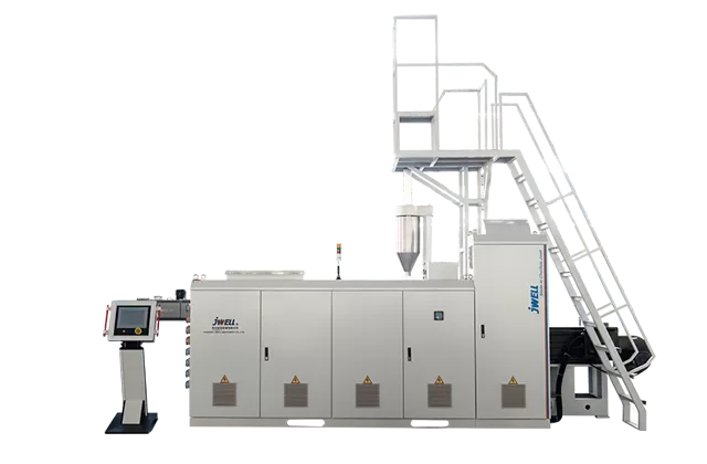
A twin screw masterbatch extruder is a continuous compounding machine that uses two rotating screws to convey, melt, mix, disperse, devolatilize, and pressurize a formulation before pelletizing. In most color, filler, and additive masterbatch applications, a co-rotating intermeshing design is preferred because its modular screw elements can be arranged to create controlled conveying, kneading, distributive mixing, and pressure-building zones.
The machine is not only a plastic melter. It is the central process reactor in which the formulation’s final dispersion, thermal history, homogeneity, and downstream usability are created. Feeders, side feeders, vent ports, melt filters, pelletizers, dryers, and control systems must therefore be engineered as one line rather than purchased as unrelated components.
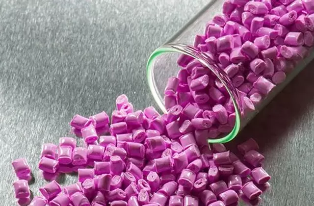
Masterbatch usually contains a higher concentration of pigment, mineral, flame retardant, stabilizer, processing aid, or another functional ingredient than the final plastic product. The processor later blends the concentrate with virgin or recycled resin at a defined let-down ratio. Because the concentrate may be diluted many times, small variations in its composition or dispersion can become visible or functional defects in the finished product.
For example, a color masterbatch containing 25% pigment and used at a 4% addition rate contributes approximately 1% pigment to the final blend:
Final pigment content = 25% × 4% = 1%
This simple calculation also shows why feeder accuracy matters. If the actual masterbatch dosage or pigment feed fluctuates, the final shade and opacity fluctuate as well.
The masterbatch compounding process is a controlled sequence that converts separate powders, liquids, and polymers into uniform, free-flowing pellets. A reliable line defines what must happen in each barrel zone and then selects equipment and operating conditions to achieve those functions without excessive residence time or shear.
Carrier resin, pigment, mineral filler, additive packages, waxes, coupling agents, and processing aids must be identified by bulk density, particle size, moisture, melting behavior, thermal stability, abrasiveness, and feeding characteristics. Materials with very different bulk densities may segregate in a premix. Hygroscopic polymers or fillers may require controlled drying. Fine powders may require dust extraction and enclosed transfer.
Loss-in-weight feeders measure the reduction in hopper mass over time and continuously correct screw speed to maintain a target mass flow. This is especially important when pigment or additive concentration directly determines the final product specification. Volumetric feeders can be suitable for stable, free-flowing materials, but their output may change as bulk density or hopper level changes.
The carrier resin enters the extruder through the main feed port and is compacted, heated, and melted. Powders can be introduced at the main feed or through a downstream side feeder. Downstream feeding can reduce dust and avoid overloading the first melting zone, but the polymer must be sufficiently molten to wet and incorporate the powder.
Distributive mixing spreads components throughout the melt without necessarily breaking particles. Dispersive mixing applies stress to break pigment or filler agglomerates. Both are required. Excessive dispersive stress can raise melt temperature, degrade resin, damage organic pigments, shorten fibers, or increase energy consumption, while insufficient stress leaves visible specks and weak color development.
Atmospheric and vacuum vents remove air, residual moisture, low-molecular-weight components, and volatile processing aids. Venting is effective only when the screw configuration creates a partially filled zone with renewed melt surface. A vacuum pump cannot compensate for a vent zone that is completely flooded.
After mixing and venting, conveying elements rebuild pressure for the die or pelletizer. A screen changer may remove contamination or oversized particles, but very fine filtration can increase pressure and temperature. The filter level should reflect the raw-material cleanliness, end-use requirement, and acceptable pressure drop.
The compounded melt is converted into strands or die-face pellets, cooled, dried, and screened. Pellet size distribution, surface moisture, fines, tails, and agglomerates affect packaging and downstream dosing. Pelletizing is therefore a quality-control stage, not merely a way to cut the extrudate.
A twin screw masterbatch extruder screw design is a modular sequence of elements selected to control fill level, melting, shear, residence time, mixing intensity, venting, and pressure. There is no universal “high-performance” screw profile because carbon black, titanium dioxide, calcium carbonate, flame retardants, glass fiber, and heat-sensitive additives impose different process demands.
| Screw element or zone | Primary function | Typical benefit | Risk if overused or misplaced |
|---|---|---|---|
| Forward conveying elements | Move material and build pressure | Stable throughput and controlled fill | Excess pressure, poor vent opening, long residence time |
| Reverse or neutral elements | Create back-mixing or a melt seal | Improved mixing and vent isolation | High torque, overheating, material stagnation |
| Kneading blocks | Apply distributive and dispersive mixing | Agglomerate breakdown and uniform composition | Pigment damage, polymer degradation, excessive specific energy |
| Large-pitch elements | Increase conveying capacity and lower fill | Useful near feed or vent zones | Insufficient pressure or weak melting if used incorrectly |
| Mixing elements | Reorient and divide melt streams | Improved distributive mixing with moderate shear | Pressure loss or unnecessary residence time |
| Pressure-building elements | Feed the filter and pelletizer | Stable die pressure and pellet formation | High discharge temperature and screen pressure |
Screw diameter indicates scale, but diameter alone does not determine capacity. Torque density, screw speed, free volume, feed-system capacity, material bulk density, required specific energy, venting load, and downstream pressure all affect achievable output. Two lines with the same nominal diameter can perform very differently when processing a low-bulk-density pigment blend or a heavily filled mineral formulation.
Length-to-diameter ratio, normally written as L/D, indicates the available processing length relative to screw diameter. A longer process section can accommodate more feeding, mixing, reaction, and venting stages, but it also increases capital cost and can increase residence time. The correct L/D is the shortest practical arrangement that still performs all required unit operations with adequate control margin.
A supplier should be able to explain the purpose of each major screw section in plain process terms. Statements such as “more kneading gives better mixing” are incomplete. The design should relate kneading angle, element width, sequence, fill level, screw speed, torque, and material temperature to measurable quality outcomes.
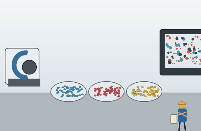
A masterbatch extruder feeding strategy is the coordinated method used to meter every component at the correct mass rate and introduce it where the extruder can process it reliably. Feeding is often the real capacity limit in formulations containing fluffy pigment, fine calcium carbonate, carbon black, or low-dose additives.
Start by converting the formulation into individual mass-flow targets. For a 1,000 kg/h line producing a formulation with 60% carrier resin, 35% mineral filler, and 5% additive package, the nominal feeder rates are:
Carrier resin: 600 kg/h
Mineral filler: 350 kg/h
Additive package: 50 kg/h
If the additive feeder varies by ±1 kg/h, its relative error is ±2%. Whether that is acceptable depends on the additive’s function and the finished-product tolerance. A similar absolute error on the main resin feeder would be far less significant. Feeder selection should therefore consider required relative accuracy, not only maximum throughput.
Bridging, rat-holing, flooding, and pulsation are common powder-feeding problems. Agitators, flexible hoppers, vertical-wall hoppers, twin-screw feeder screws, refill control, and conditioned air can improve stability. However, mechanical agitation that is too aggressive can compact some powders and make flow worse. Feeder trials with the actual raw material are more valuable than generic assurances.
Premixing can simplify the number of feeders, but it can also create segregation. A dense mineral may settle while a low-density pigment remains near the top of the mixer or transfer line. Separate gravimetric feeding often provides better formulation control, while a properly validated premix can reduce investment and cleaning time for simpler products.
Liquid additives require heated tanks, agitation, metering pumps, insulated lines, and injection nozzles designed to prevent leakage and blockage. The injection point should provide enough melt pressure to stop backflow while allowing rapid incorporation. Temperature-sensitive liquids may need downstream injection to reduce exposure time.
A compounding extruder process window is the range of feed rate, screw speed, barrel temperature, torque, melt temperature, pressure, and vacuum conditions that produces acceptable quality at a stable operating cost. Operators should control the actual process response rather than assume that barrel setpoints equal material temperature.
Polymer is heated by both barrel heaters and mechanical work. At higher screw speed or stronger mixing, viscous dissipation can generate substantial heat even when heater output decreases. Melt temperature at the discharge is therefore a key measurement. A line can have apparently normal zone setpoints while the compound is overheating internally.
Specific mechanical energy provides a useful way to compare runs:
SME (kWh/kg) = net motor power (kW) ÷ output (kg/h)
For example, if the drive contributes 180 kW net power at 900 kg/h, SME is 0.20 kWh/kg. If output falls to 700 kg/h while power remains 180 kW, SME rises to approximately 0.257 kWh/kg. The increase may improve dispersion, but it may also indicate feed restriction, excessive kneading, poor lubrication, or an unnecessarily severe screw profile.
Torque should be interpreted together with screw speed and output. High torque at low speed may indicate a cold, highly filled, or poorly lubricated formulation. Low torque with poor dispersion may mean the barrel is underfilled or the mixing section is not engaging enough material. A stable process normally shows repeatable feeder rates, torque, melt pressure, melt temperature, and vacuum load rather than large oscillations around an acceptable average.
Temperature profiles should support the sequence of operations. The feed zone may need cooling to prevent premature melting and feed-port bridging. The melting zone must soften the carrier without creating unmelted resin. Mixing zones may require cooling because mechanical energy generates heat. The discharge zone must provide a stable viscosity for filtration and pelletizing.
Pelletizing selection is the decision that matches melt behavior, output, cleanliness, product-change frequency, pellet specification, and operating skill to a cutting and cooling method. No pelletizer is universally superior; the correct system is the one that remains stable with the intended formulation range.
| Pelletizing method | Best suited to | Main advantages | Main limitations |
|---|---|---|---|
| Strand pelletizing | Stable formulations, moderate output, frequent product changes | Simple process visibility, easier cleaning, comparatively flexible | Strand breaks, operator attention, water carryover, less suitable for very sticky or brittle strands |
| Water-ring pelletizing | Many polyolefin and filled compounds | Compact layout, automated die-face cutting, good output capability | Die buildup, sensitivity to melt strength and blade condition, changeover cleaning |
| Underwater pelletizing | High output, sticky materials, demanding pellet uniformity | Enclosed cutting, good pellet shape, broad high-throughput potential | Higher capital cost, more auxiliary equipment, tighter startup and maintenance control |
| Air-cooling hot cut | Water-sensitive materials or selected formulations | Avoids water contact and drying load | Dust, heat management, narrower material window |
Strand systems are often a practical starting point for plants with many colors and frequent cleaning because the die, water bath, air knife, and cutter are easy to inspect. However, a formulation with weak melt strength may break repeatedly. Water-ring systems reduce manual strand handling but require stable die pressure and clean die holes. Underwater systems can handle high output and difficult melts, but startup procedures, water temperature, cutting-chamber pressure, blade adjustment, and drying capacity must all be controlled.
Pellet quality should be specified numerically where possible. Useful acceptance measures include average pellet dimensions, percentage of fines, percentage of oversize pellets, surface moisture, bulk density, and the number of tails or agglomerates in a defined sample mass. “Uniform pellets” is not an adequate purchase specification.
Masterbatch quality control is a set of repeatable tests that verifies composition, dispersion, processing stability, pellet condition, and end-use performance. Testing only pellet appearance is insufficient because a glossy, uniform pellet can still contain poorly dispersed pigment or an incorrect additive concentration.
Verify resin grade, melt-flow behavior, moisture, pigment strength, filler particle characteristics, additive identity, and certificate data. Retain samples and use lot traceability. Changes in pigment surface treatment, mineral moisture, carrier viscosity, or recycled-content quality can shift the process even when the formulation percentages remain unchanged.
Record feeder rates, refill events, torque, screw speed, motor load, melt temperature, melt pressure, vacuum level, screen pressure, output, and pelletizer conditions. Trends are often more informative than a single reading. A gradual pressure increase may indicate screen loading, degradation, contamination, or die-hole restriction.
Measure color difference, dispersion, moisture, bulk density, ash content for filler products, melt flow, pellet-size distribution, fines, and contamination. The test method should reflect the product. Carbon black dispersion may require microscopy or a pressure-filter test. Color masterbatch may require plaques or film prepared at a controlled dilution, thickness, resin grade, and processing condition.
The most meaningful test is performance in a representative downstream process. A masterbatch intended for blown film should be checked for dispersion, filter pressure, film appearance, gauge stability, and mechanical impact under film-processing conditions. A formulation intended for fiber requires much tighter filtration and particle control than one intended for thick injection-molded parts.
Color measurement should define illuminant, observer angle, instrument geometry, sample preparation, thickness, substrate, and acceptance tolerance. Without a standardized preparation method, two samples can produce different readings because of plaque thickness, surface texture, orientation, or cooling history rather than formulation variation.
Masterbatch troubleshooting is the disciplined process of linking an observed defect to material, feeding, mixing, venting, filtration, pelletizing, or handling causes before changing operating settings. Changing several parameters at once may temporarily hide a problem but prevents the plant from learning which variable actually controlled the result.
| Observed defect | Likely causes | Checks | Corrective direction |
|---|---|---|---|
| Color streaks or specks | Weak dispersion, feeder variation, contamination, incompatible carrier | Dispersion test, feeder trend, cleaning record, dilution resin | Improve wetting and mixing, stabilize feed, validate carrier compatibility |
| Black or burnt particles | Material stagnation, excessive melt temperature, dead zones, long residence time | Melt-temperature trend, screw and die inspection, shutdown procedure | Reduce thermal severity, remove dead zones, improve purging |
| Unstable pellet size | Pressure fluctuation, feeder pulsation, blade wear, inconsistent cooling | Melt-pressure trend, feeder output, cutter speed, water temperature | Stabilize feed and pressure, service cutting system, control cooling |
| High fines | Brittle strands, incorrect cutter gap, excessive drying or impact | Strand temperature, blade condition, pellet transport | Adjust cooling and cutting, reduce harsh conveying |
| Vent material carryover | Overfilled vent zone, poor screw design, excessive feed, unstable melting | Fill level, side-feed rate, vent-zone elements, vacuum line | Create an open vent zone, rebalance feed and screw configuration |
| Rising screen pressure | Contamination, degradation, poorly dispersed agglomerates, filter too fine | Screen residue, melt temperature, dispersion, raw-material cleanliness | Correct root material or mixing issue; optimize filtration level |
| Low output at high torque | Feed restriction, excessive filler, cold melt, severe screw profile | Feeder capacity, bulk density, lubrication, temperature, SME | Improve feeding, adjust formulation or screw design, optimize temperature |
| Odor or bubbles | Moisture, volatiles, degradation, inadequate venting | Drying records, vacuum level, condensate, residence time | Improve drying and venting; reduce thermal exposure |
A useful troubleshooting rule is to separate composition variation from dispersion variation. If ash content or analytical concentration changes, investigate feeding, refill control, segregation, or formulation. If concentration is correct but visible performance changes, investigate wetting, mixing, carrier compatibility, filtration, and sample preparation.
Another useful distinction is whether a defect appears continuously or intermittently. Continuous defects usually reflect a stable mismatch such as insufficient mixing or wrong temperature. Intermittent defects often point to feeder refill cycles, bridging, contamination release, vent flooding, unstable die pressure, or pelletizer events.
Line sizing is the calculation that converts annual saleable output, operating time, product mix, changeovers, and demonstrated formulation capacity into a practical equipment requirement. Selecting a line only by a supplier’s maximum kg/h figure can lead to an undersized feeding system, excessive cleaning loss, or a machine that reaches nameplate output only on an easy resin grade.
Assume a plant needs 6,000 tonnes of saleable masterbatch per year. It plans to run 300 days, 20 scheduled hours per day, with 82% effective utilization after changeovers, maintenance, trials, and unplanned stops:
Required average saleable rate = 6,000,000 kg ÷ (300 × 20 × 0.82) ≈ 1,220 kg/h
This number is the average saleable output, not merely instantaneous extrusion rate. If startup scrap, screen changes, off-spec transitions, and pellet fines equal 3%, the gross production rate must be approximately:
Gross rate = 1,220 ÷ 0.97 ≈ 1,258 kg/h
The selected line should demonstrate this rate on the relevant formulation while maintaining torque, melt temperature, pressure, dispersion, and pellet quality within agreed limits. If the plant produces many small color lots, changeover time may matter more than maximum rate. Two smaller lines can sometimes provide better scheduling flexibility and contamination control than one large line, although they require more floor space, operators, and maintenance points.
Auxiliary equipment must be sized for the same realistic condition. A 1,200 kg/h extruder cannot deliver 1,200 kg/h when the side feeder handles only 300 kg/h of a formulation requiring 40% filler. Cooling-water, vacuum, dryer, classifier, conveying, and packaging systems also need adequate capacity and turndown.
A masterbatch line supplier should be evaluated by its ability to convert formulation requirements into a testable process configuration, not only by machine size, motor power, or quoted output. A capable supplier asks for raw-material data, product range, target dispersion, pelletizing preference, cleaning requirements, utilities, automation level, and acceptance criteria before finalizing the line.
Important supplier evidence includes application trials, screw-configuration logic, feeder experience, wear-material selection, control integration, safety documentation, spare-parts support, commissioning scope, and references from comparable materials. For abrasive calcium carbonate or titanium dioxide products, barrel liners, screw metallurgy, side-feeder wear, and replacement strategy require specific discussion. For frequent color changes, cleanability and material hold-up deserve equal attention.
JWELL presents itself as a large-scale plastic extruder manufacturer with multiple production bases and engineering resources. Its company profile states that the group was founded in 1997, operates eight production bases totaling more than 700,000 square meters, employs more than 3,000 people, and has around 300 engineers supporting overseas markets. Buyers should still validate the proposed configuration with their own materials and acceptance tests, but this manufacturing and service scale is relevant when evaluating project execution and lifecycle support.
When comparing proposals, separate the process system from optional commercial scope. A complete comparison should list feeders, mixer or premix system, main extruder, side feeder, liquid dosing, venting, vacuum, screen changer, pelletizing, cooling, drying, classification, conveying, packaging interface, control system, electrical standard, safety guarding, installation supervision, commissioning, training, spare parts, and performance test.
JWELL’s compounding machine category can be used to review available line families, while its broader plastic extrusion equipment navigation helps procurement teams compare compounding with sheet, pipe, profile, recycling, and other downstream systems when planning an integrated factory.
A factory acceptance test is a documented production trial that verifies the agreed formulation, output, quality, energy, controls, safety functions, and changeover behavior before shipment. The test should be written into the purchase specification so that both buyer and supplier know how success will be measured.
A strong FAT protocol identifies the raw-material supplier and grade, formulation percentages, batch preparation, feeder calibration method, run duration, stabilization period, target output, maximum torque, screw speed, melt-temperature limit, pressure range, vacuum requirement, pellet dimensions, moisture, fines, dispersion test, color tolerance, sampling frequency, and reporting format.
One short demonstration after the machine reaches stable operation may not reveal refill-cycle variation, screen-pressure rise, thermal drift, vent contamination, or pelletizer wear. A longer run provides better evidence of stability. The protocol should also define what happens if the buyer’s raw material is unavailable and a substitute is used; results from a substitute formulation should not automatically be treated as proof for the production recipe.
Recommended FAT records include:
Calibrated feeder rates and refill trends for every ingredient
Output measured by timed mass collection or verified packaging data
Screw speed, torque, motor load, and calculated SME
Barrel setpoints and measured melt temperature
Melt pressure before and after filtration where available
Vacuum level and observations at each vent
Pellet size, fines, moisture, bulk density, and visual contamination
Dispersion, color, ash, melt flow, or other product-specific test results
Alarm, interlock, emergency stop, guarding, and safe-access checks
Startup, shutdown, cleaning, recipe storage, and data-export demonstration
Acceptance should be based on saleable product, not only material passing through the die. If 1,000 kg enters the line but 40 kg becomes startup waste, wet agglomerates, or classifier rejects, the saleable yield is 96%. This directly affects unit cost and should be considered alongside rated throughput.
These frequently asked questions define the practical issues buyers most often need to resolve before selecting or operating a masterbatch compounding line.
Its intermeshing modular screws provide strong self-wiping, flexible feeding positions, controlled distributive and dispersive mixing, effective venting, and configurable pressure zones. This makes it suitable for formulations containing pigments, fillers, and additives that require more intensive mixing than a conventional single-screw process.
Output depends on screw diameter, torque, screw speed, free volume, formulation bulk density, feeder capacity, filler level, required dispersion, venting, filtration, and pelletizing. A supplier should demonstrate output with a representative formulation; a capacity stated for neat resin may not apply to a low-density or highly filled masterbatch.
There is no single best L/D. The line needs enough length for feeding, melting, side feeding, mixing, venting, and pressure building without unnecessary residence time. Complex reactive or multi-feed formulations may require more process length than a simple color concentrate.
The let-down ratio depends on concentrate strength, target color or function, carrier compatibility, final product thickness, and supplier recommendations. Some concentrates are used below 1%, many color systems are used at a few percent, and certain functional or heavily filled systems can require much higher levels. The dosage must be validated in the actual downstream process.
Use a line designed with low material hold-up, accessible feed and pelletizing components, appropriate screw self-wiping, validated purge materials, clear color sequencing, and documented shutdown procedures. Production scheduling from light to dark colors and from compatible to difficult formulations can also reduce waste.
Include actual formulation, stable saleable output, feeder accuracy, torque, melt temperature, pressure, vacuum, pellet quality, dispersion or color performance, moisture, fines, safety interlocks, and cleaning or recipe-change functions. Acceptance limits should be numeric and agreed before the test.
The correct masterbatch line begins with the formulation and finished-product requirement, not with a generic extruder model. Material flow determines feeder design. Carrier viscosity and additive behavior determine melting and mixing. Dispersion targets determine screw elements and specific energy. Moisture and volatiles determine venting. Melt strength and output determine pelletizing. Product diversity determines cleaning and automation priorities.
A technically sound project therefore links every equipment choice to a measurable result: stable ingredient mass flow, controlled torque and melt temperature, adequate dispersion, repeatable composition, low contamination, uniform pellets, acceptable energy use, and high saleable yield. These results should be proven through representative material trials and a documented factory acceptance test.
JWELL can support projects that require feeder integration, modular twin-screw processing, venting, filtration, pelletizing, automation, and downstream handling. To receive a useful technical proposal, provide the formulation range, raw-material data, target output, pellet specification, quality tests, utility conditions, available floor space, electrical standard, automation expectations, and desired FAT criteria.
The following independent resources provide additional technical and industry context:

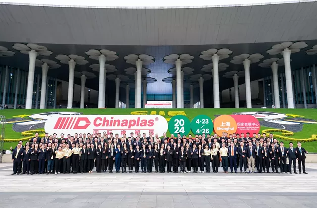
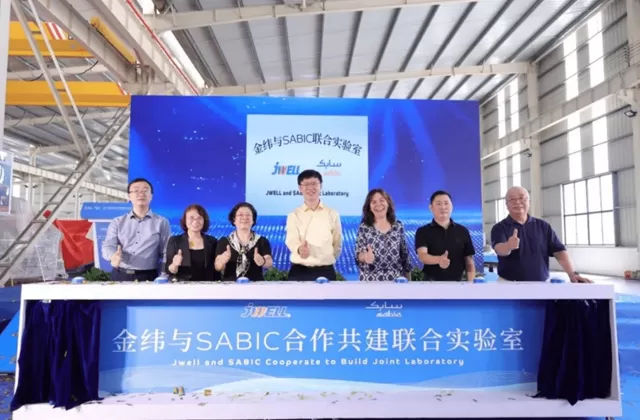

Jwell started manufacturing screws and barrels in 1978, making it one of the earliest screw and barrel manufacturers in China. Its brand, "Jinhailuo", has become well recognized in the industry. In 1997, Jwell was established as a plastic extrusion machinery manufacturer and began the production of extrusion machinery. Today, Jwell is the vice president unit of the China Plastics Machinery Industry Association and one of the technology leaders in the extrusion machinery industry.